The growing need for new roads may, in many cases, require construction over soft or loose soils that are incapable of supporting additional loads. Designers must identify innovative materials and construction techniques to address the problem of building on soft soils or where sensitive existing utilities or wetlands are present while, at the same time, accelerating project schedules. EPS geofoam can be used to replace compressible soils or in place of heavy fill materials to prevent unacceptable loading on underlying soils and adjacent structures. The high compressive resistance of EPS geofoam makes it able to adequately support traffic loadings associated with secondary and interstate highways. Construction with EPS geofoam also saves time because EPS geofoam is easy to handle without the need for special equipment. Because EPS geofoam is an engineered product it arrives on site already having undergone rigorous Q&A testing, unlike other fill materials that require time consuming QA/QC testing.
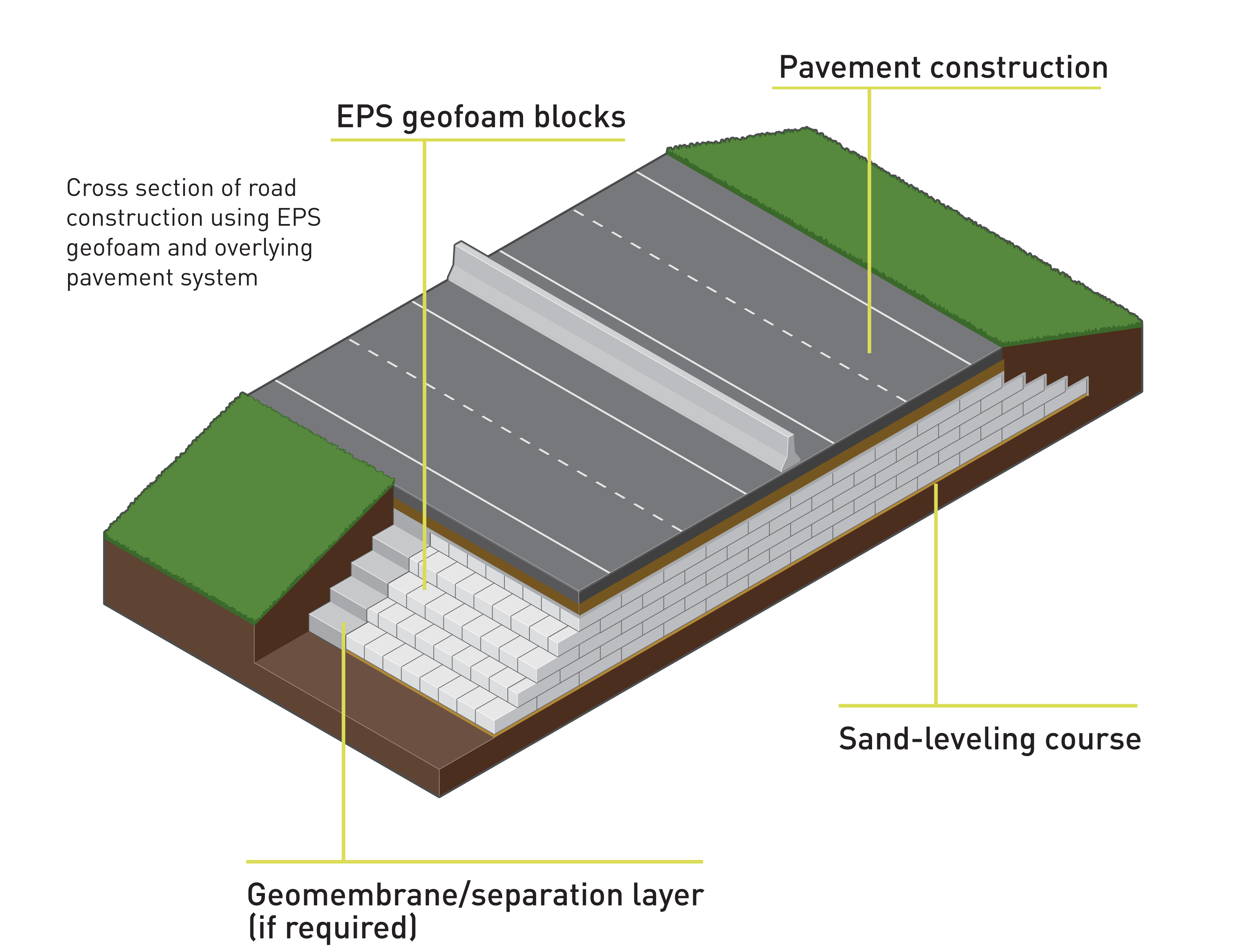
A description of a typical road construction, from bottom to top, is as follows: compact a layer of sand at the base of the roadway excavation to provide a level and free draining construction surface. Place the EPS geofoam to the desired height, staggering the vertical joints in each course so as not to create continuous vertical seams.
If required, a separation layer may be placed between the top of the EPS geofoam and the overlying pavement system. A separation layer can have two functions: to enhance the overall performance and life of the pavement system by providing reinforcement, separation and/or filtration and to enhance the durability of the EPS geofoam both during and after construction. Choices for the separation layer include geotextile, hydrocarbon resistant geomembrane, geogrid, geocell with soil fill, soil cement, pozzolanic stabilized materials or a reinforced concrete slab.
For example, if protection against fuel spills is desired, a hydrocarbon resistant geomembrane cover can be placed over the uppermost EPS block course to protect from possible hydrocarbon attack. Alternately, a reinforced concrete load distribution slab can be used to protect the EPS geofoam from hydrocarbon attack and from potential overstressing resulting from heavy traffic loads. Other structural features (i.e., tilt-up panel walls, impact barriers, light and power poles, etc.) can be anchored to the load distribution slab.
The pavement system, which generally consists of select fill, roadbase gravel and an asphalt or concrete pavement driving surface, is subsequently constructed atop the separation layer. Prevention of differential icing is a consideration when using EPS geofoam in roadway construction in cold climates. Differential icing is defined as the formation of ice on the surface of an insulated pavement, when the adjacent, non-insulated pavement remains ice-free. When constructed next to existing roadways, sections of pavement constructed over EPS geofoam can form ice prior to adjoining areas because EPS geofoam is an excellent insulator, which prevents heat from reaching the pavement from the underlying soil. One way to address this concern is to keep the top level of the EPS geofoam at or below the appropriate frost line for the region. For example, for a frost line of 3 feet (0.9 meters), a minimum separation layer and pavement system material thickness of 3 feet (0.9 meters) should be provided over the EPS geofoam.
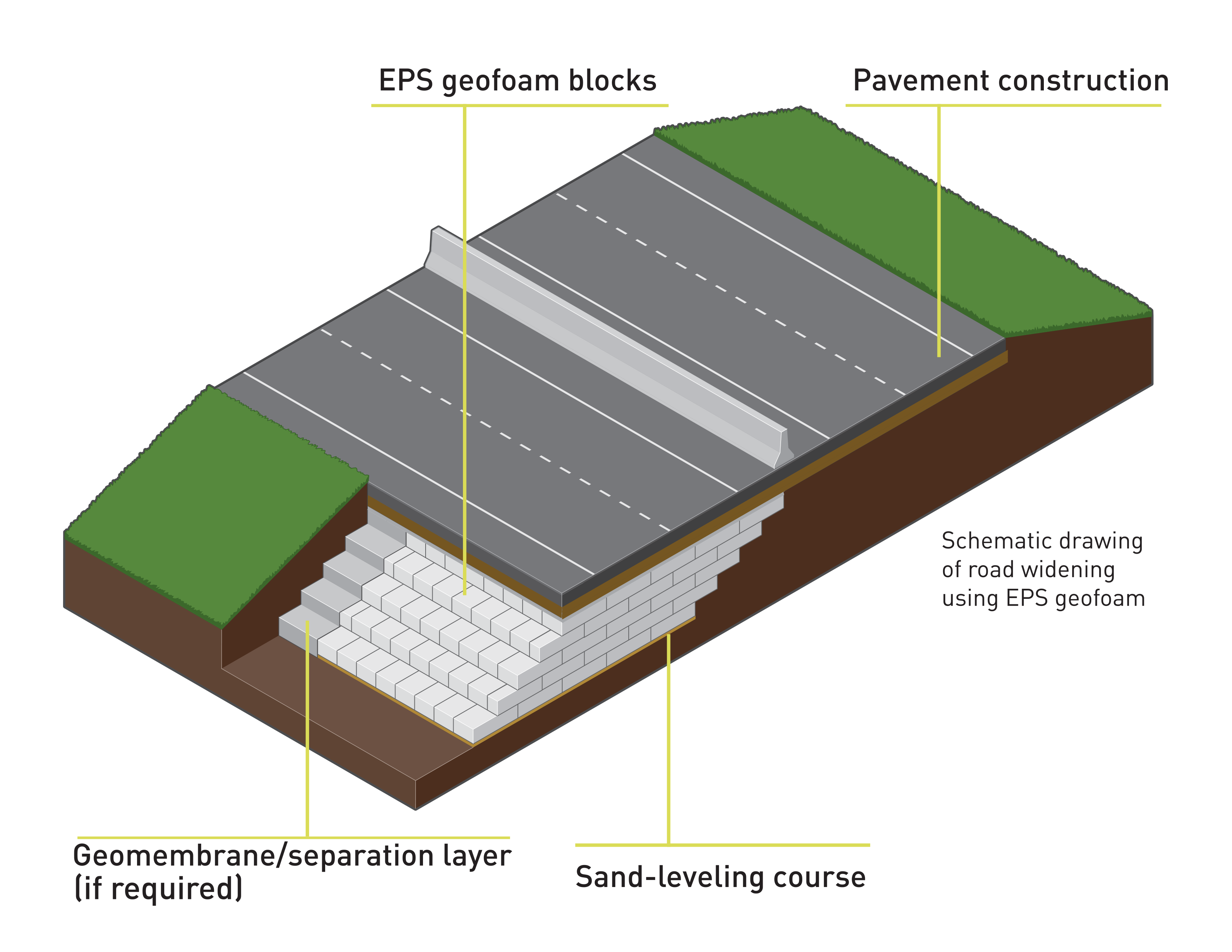
Roadways often have to be widened to reduce congestion. This situation results in additional fill being required for the roadway to be widened. This can be an expensive and time-consuming process if the soils adjacent to the existing roadway are not adequate to support the traffic loads because the resulting settlement can impact the existing roadway. In traditional construction, soil embankments are built in thin lifts, each of which must be compacted before the next lift is placed. Using EPS geofoam eliminates the need for compaction and fill testing, reduces the construction time and minimizes impact to the existing roadway and adjacent structures and/or buried utilities. The high compressive resistance of EPS geofoam makes it able to withstand the induced traffic forces without causing unacceptable loading of the underlying soils or adjacent fill. In addition, it may be possible to build steeper slopes using EPS geofoam than soil, which can reduce the amount of additional right-of-way that needs to be acquired.
The largest EPS project in the United States was the widening of I-15 in Salt Lake City, Utah where, from 1997 to 2001, approximately 130,800 cubic yards (100,000 cubic meters) of EPS geofoam was used to reconstruct parts of the interstate to facilitate the 2002 Winter Olympics.
In some locales, numerous pre-existing buried utility lines traversed or paralleled the interstate in the widened areas. These utilities consisted of high pressure gas lines, water mains and communication cables, all of which needed to remain in-service during construction. However, placement of conventional soil for the embankments in the widened areas would have produced as much as 3.3 to 4.9 feet (1 to 1.5 meters) of settlement, thus exceeding the strain tolerances of the buried utilities. The use of EPS geofoam in the utility areas essentially eliminated these large and damaging settlements and allowed construction to proceed rapidly without expensive interruption, replacement or relocation of the utilities.
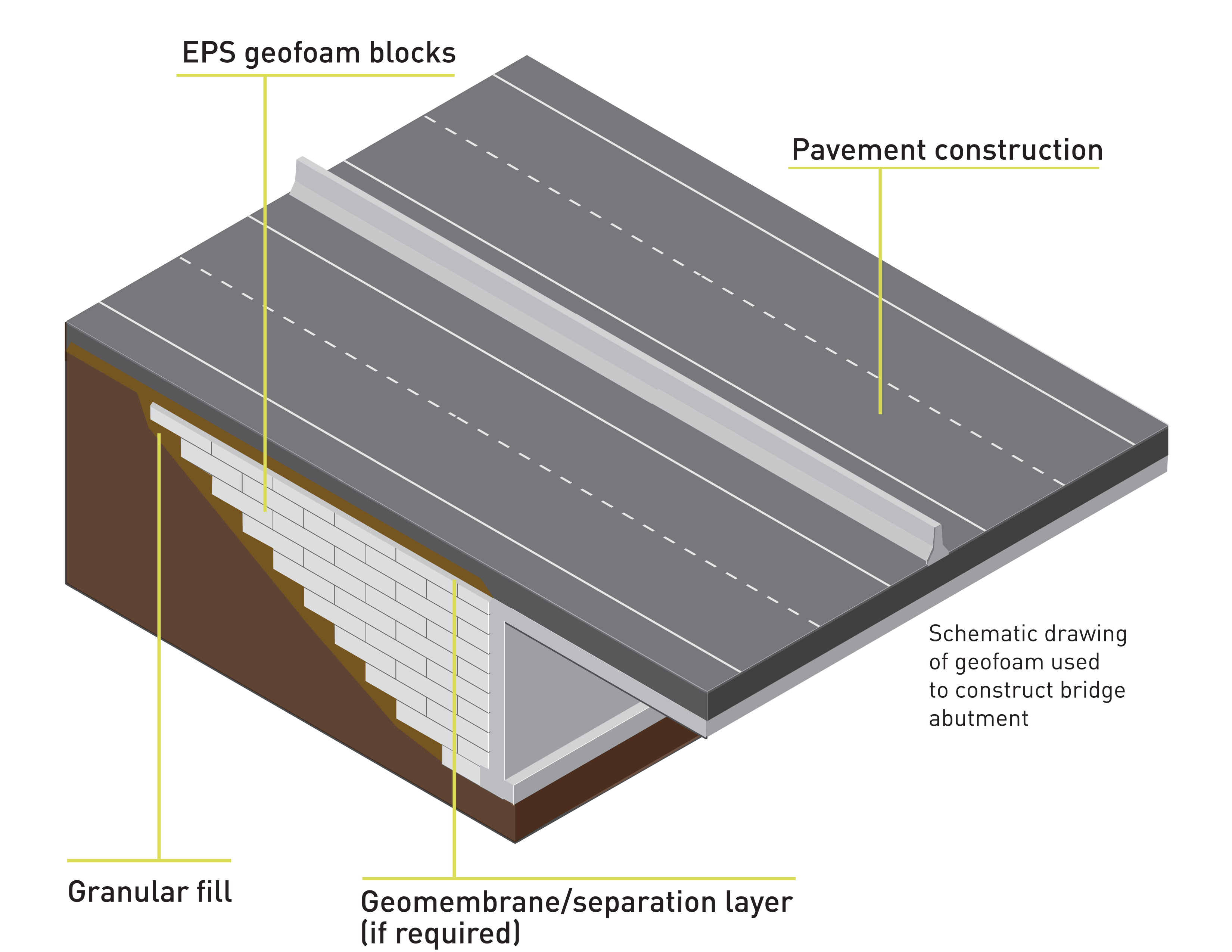
There are several advantages to using EPS geofoam to construct approach fills for bridge abutments. Because of its high compressive resistance, EPS geofoam can safely support highway loading without over-stressing the underlying soils. This usually results in less differential movement at the bridge/approach fill interface, which reduces the construction cost of the approach slab and its long-term maintenance. In addition, when compared to traditional embankment fills, EPS geofoam imparts significantly reduced lateral forces on abutment walls, foundations and other retaining structures, because the transmitted lateral force is proportional to the weight of the backfill. If this weight is substantially reduced, as with the case of EPS geofoam backfill, this leads to savings in the design of bridge abutment and other walls, which are no longer required to resist large horizontal static and dynamic forces.
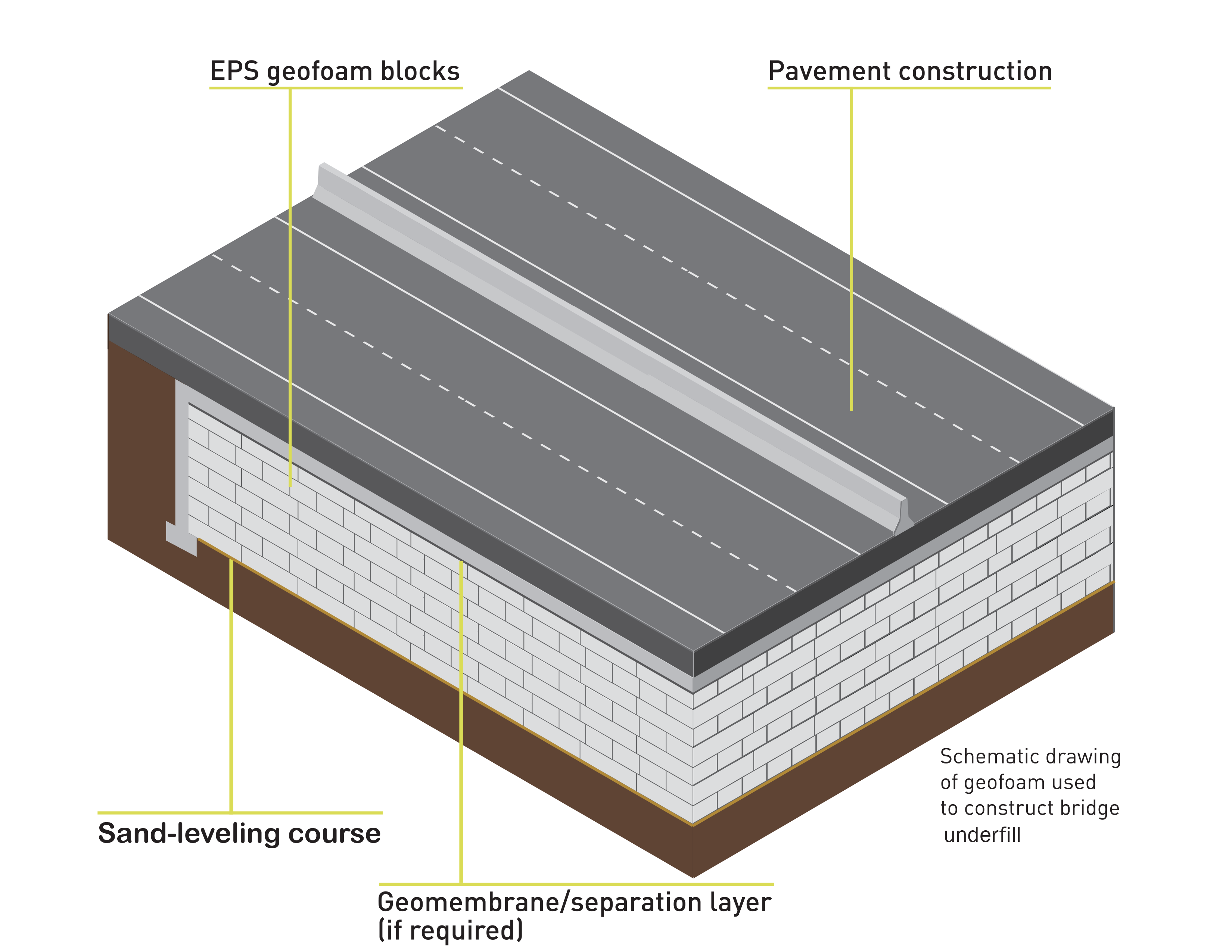
EPS geofoam can be used to support bridges when properly designed. EPS geofoam’s light weight adds little additional load to the underlying ground. In cases where the existing bridge is no longer structurally capable of carrying the required traffic loads, EPS geofoam infill can help support the span and transfer the traffic load safely to the foundation or underlying soil.
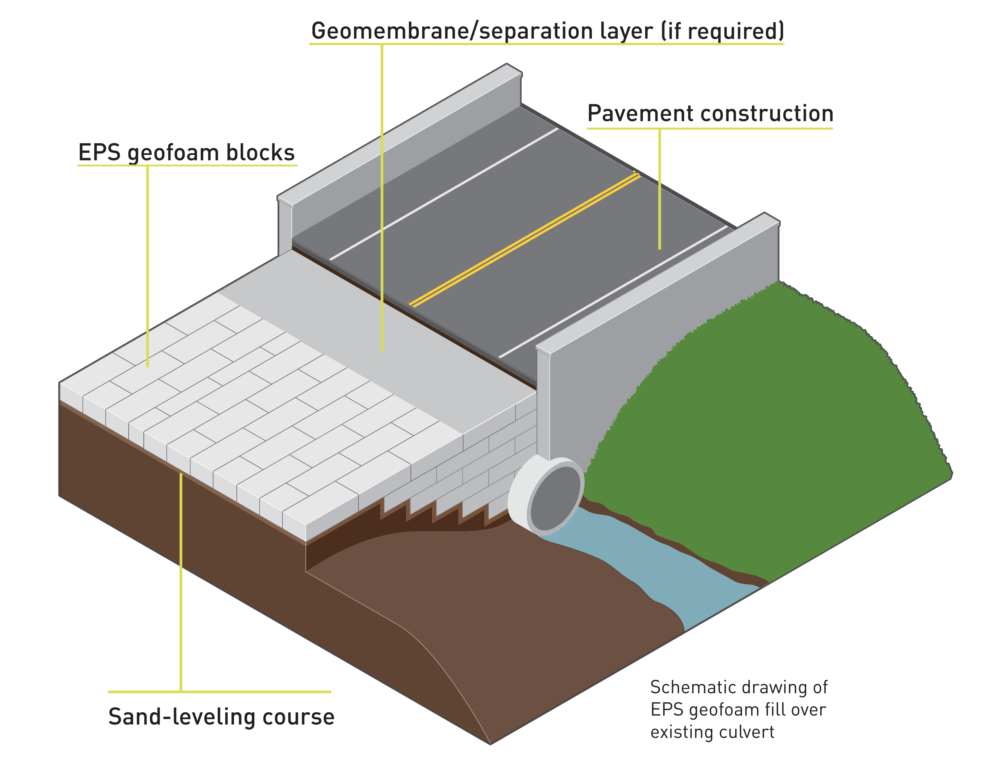
Engineering plans often call for the placement of new fill over existing underground structures that were not designed to support the increased loads. Rather than removing or strengthening the existing underground structures, the new fill load can be reduced to a tolerable level by using EPS geofoam instead of heavier traditional fills.
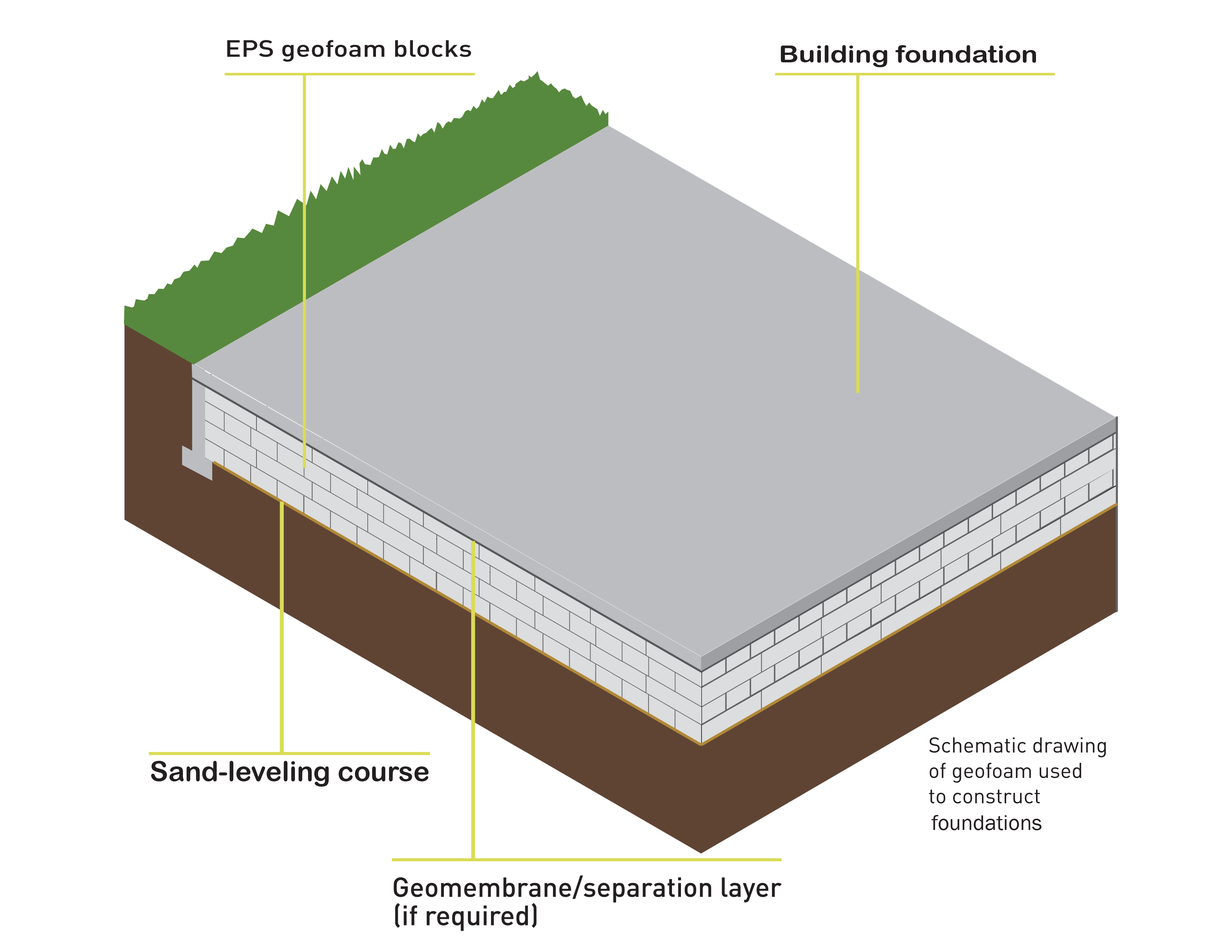
EPS geofoam can be used as a compensating foundation to reduce the load on underlying compressible soils and minimize building settlement along with potential bearing capacity problems. Existing soil is excavated to reduce the net applied load to the soil by the new structure. If the amount of soil excavated equals the full weight or stress applied by the new structure, the foundation is called “floating” or “fully compensating”.
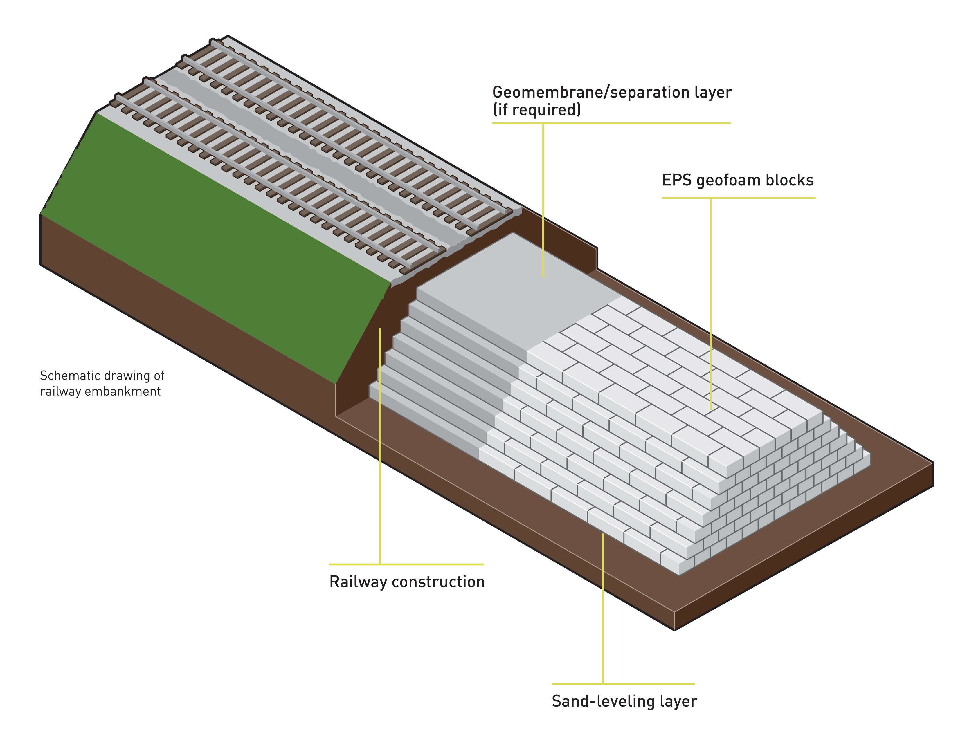
The U.S. Federal Highway Administration has urged all states to consider alternate materials when planning fill and embankment projects. EPS geofoam can be used to construct railway embankments that do not overload the existing soils. As a fill material, EPS geofoam is strong enough to support railway loads.
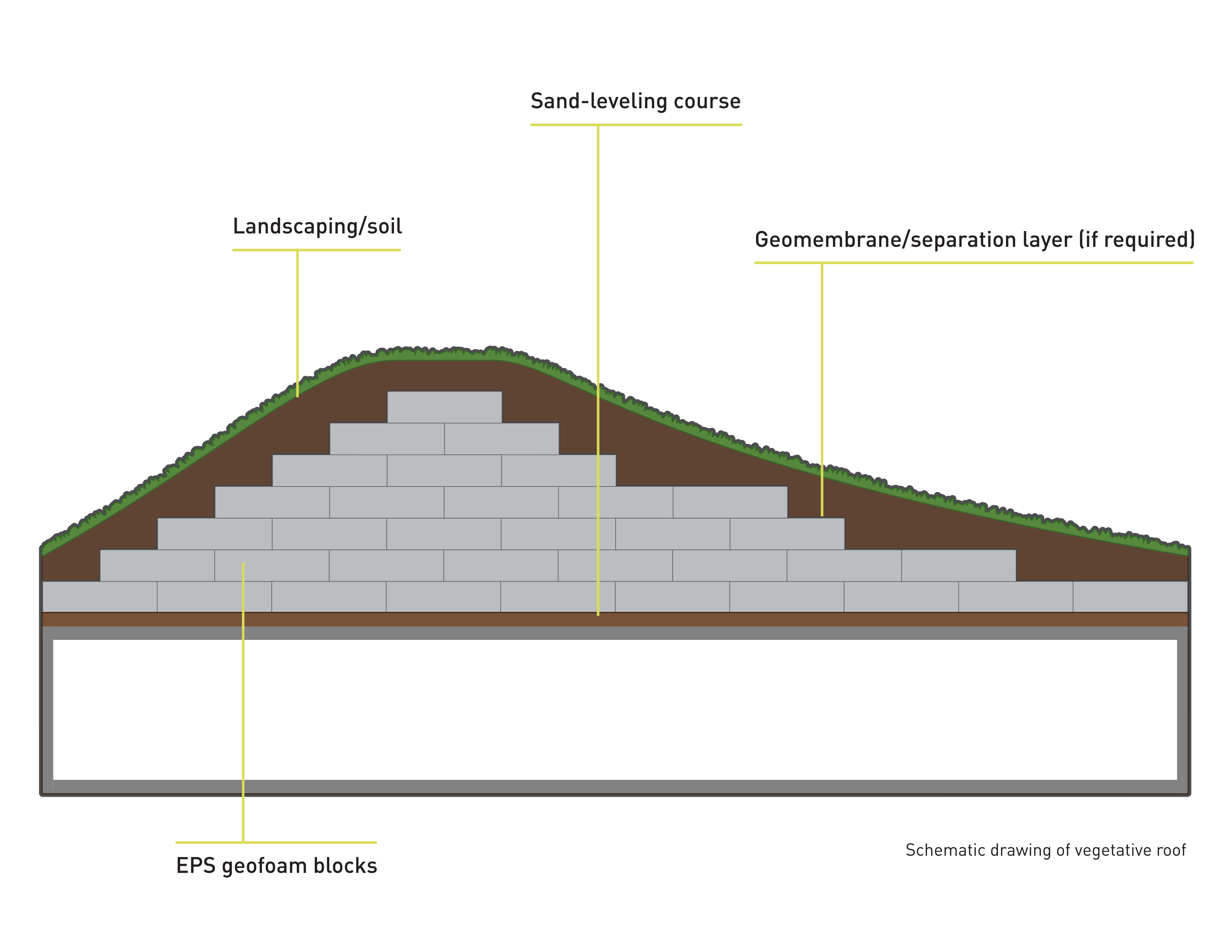
EPS geofoam can be used to create topography without adding significant load to underlying structures and services. Some examples of this application include creating roof gardens for urban buildings.
Vegetative roofs provide many benefits to a building, especially in urban areas. They reduce runoff by managing rainwater, improve air quality and reduce air temperatures. EPS geofoam is ideal for this application because it can be cut or trimmed to fit odd geometries, can be installed on the roof without special equipment and does not add any appreciable load to the roof structure.
EPS geofoam can be cut and shaped on site to create interesting architectural and landscape profiles. An added benefit of using EPS geofoam for a vegetative roof is the additional insulation value it provides.
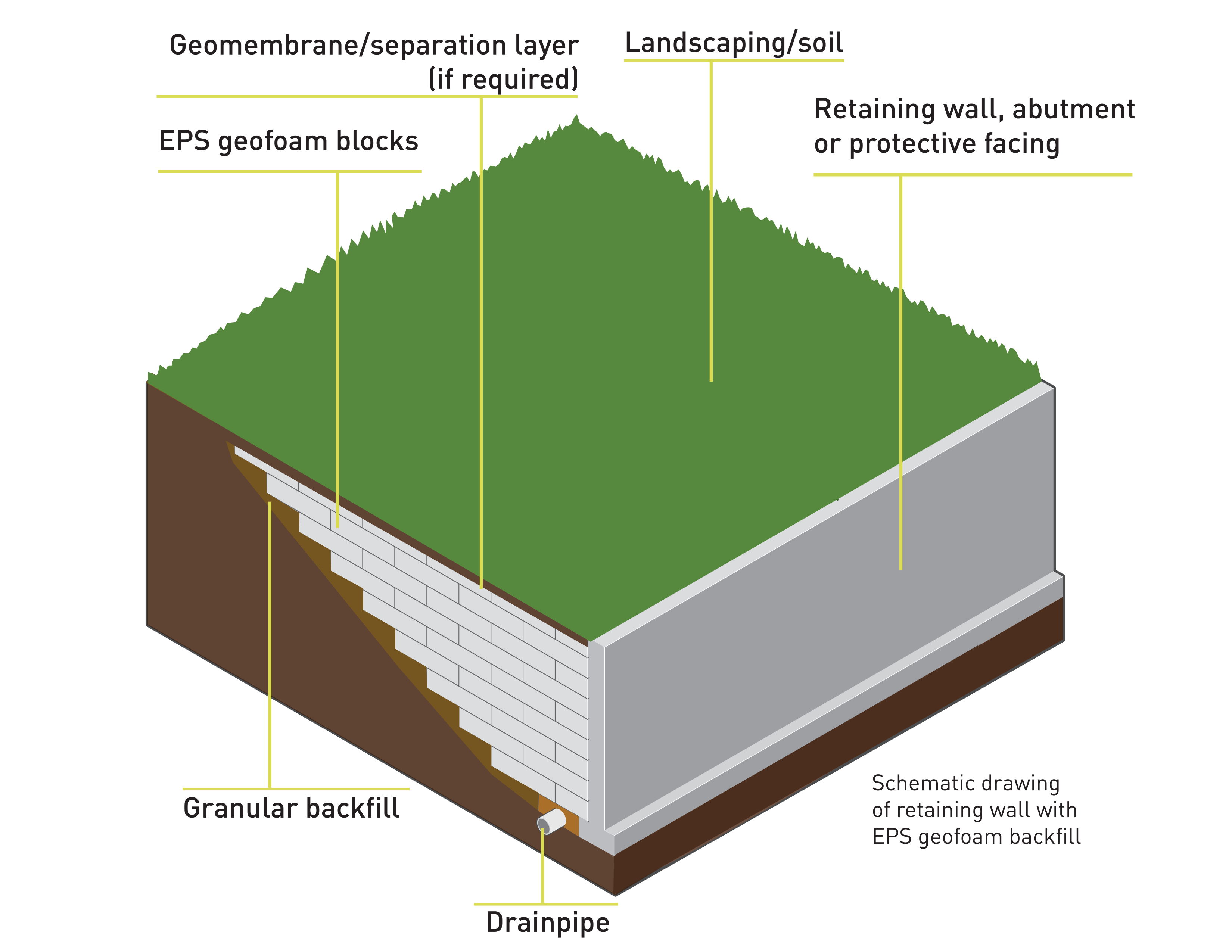
EPS geofoam can be used as backfill behind retaining and buried structures to greatly reduce lateral pressures on the structure. Because the horizontal pressure acting on a retaining wall is proportional to the weight of the backfill, a less robust retaining structure is needed if the backfill soil in the active zone behind the retaining wall is replaced with EPS geofoam.
Likewise, the use of EPS geofoam backfill behind retaining and buried structures also limits the horizontal forces that can develop during earthquakes. In retaining wall applications, adequate drains should be provided to prevent the development of hydrostatic pressure and uplift due to buoyancy for sites with shallow groundwater and loose soils.
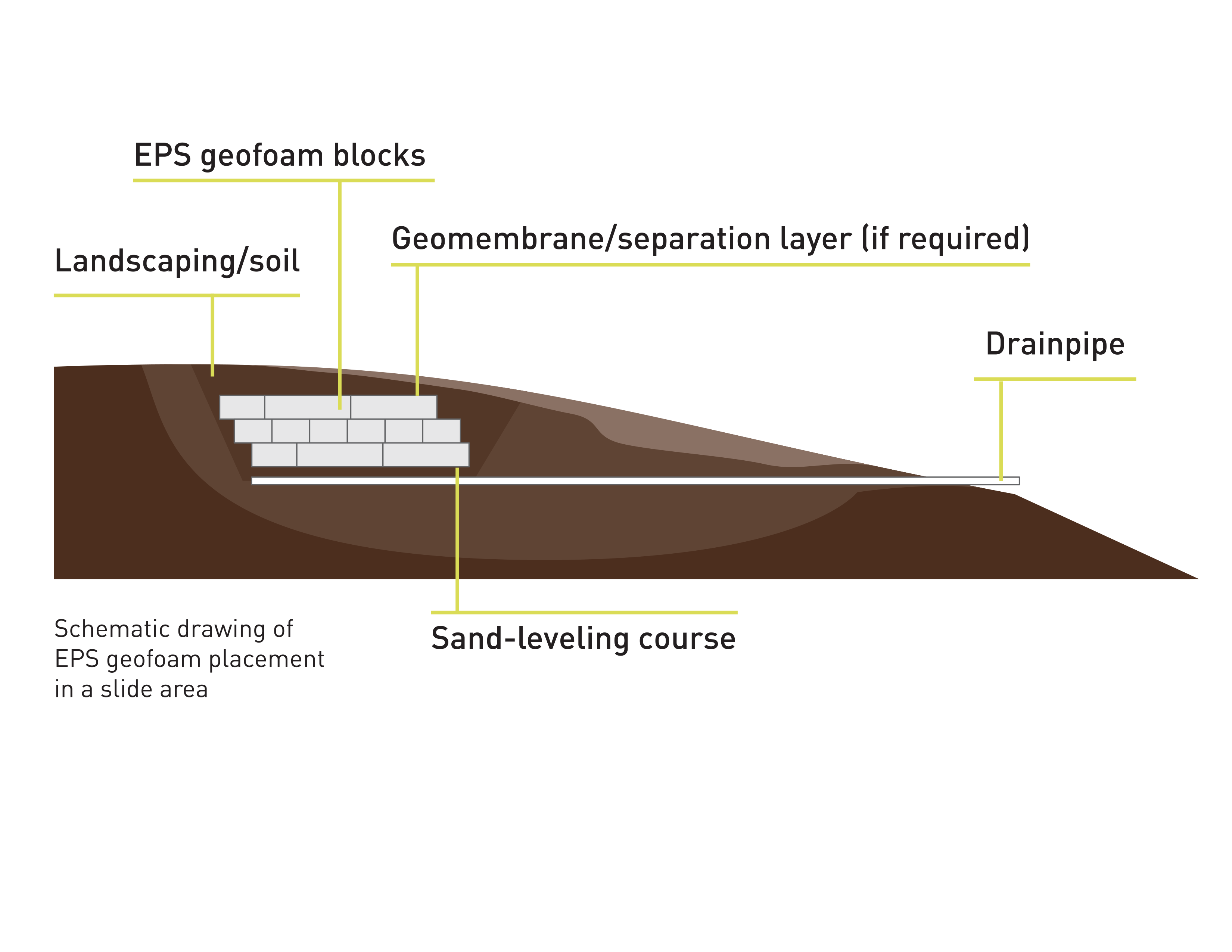
Unstable slopes can be remediated by removing a portion of the existing soil and replacing it with lightweight EPS geofoam, thus unloading the head or top of the landslide and improving its stability. With this method, the entire slide mass may not need to be excavated and replaced to achieve the desired factor of safety against future sliding, which can lead to significant time and cost savings. EPS geofoam can be used for slope stabilization and repair in both soil and rock slopes.
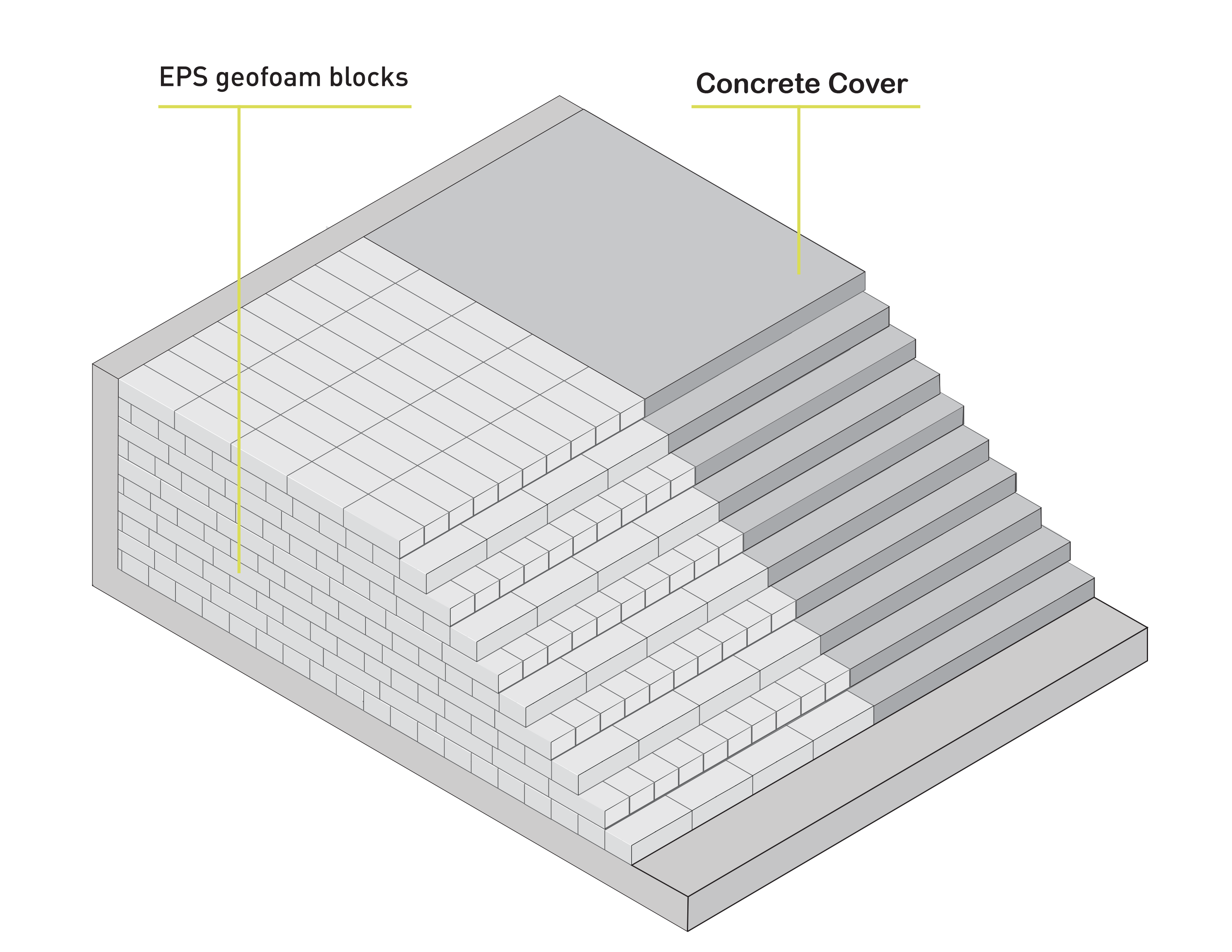
EPS geofoam can be used to form tiered seating in locations such as auditoriums, movie theaters, gymnasiums and churches. The high compressive resistance and light weight of EPS geofoam make it well suited to both new construction and renovation projects.
For these projects, the EPS geofoam blocks are fabricated and then stacked to create the desired profile. Fascia riser screeds are attached to the front of the blocks and provide formwork for the placement of finished concrete treads. Seats, bleachers and other attachments and finishes are then added to complete the project.
Levees are frequently built on compressible alluvial soils along rivers because of river depositional patterns. These compressible and saturated soils settle over time due to primary and secondary compression. This continued settlement results in the levee having to be repeatedly raised to provide the desired flood protection. Levees are usually raised with conventional soil fill to return the levee to its original level. The extra weight from the levee raising causes additional settlement and the cycle of settlement and raising continues.
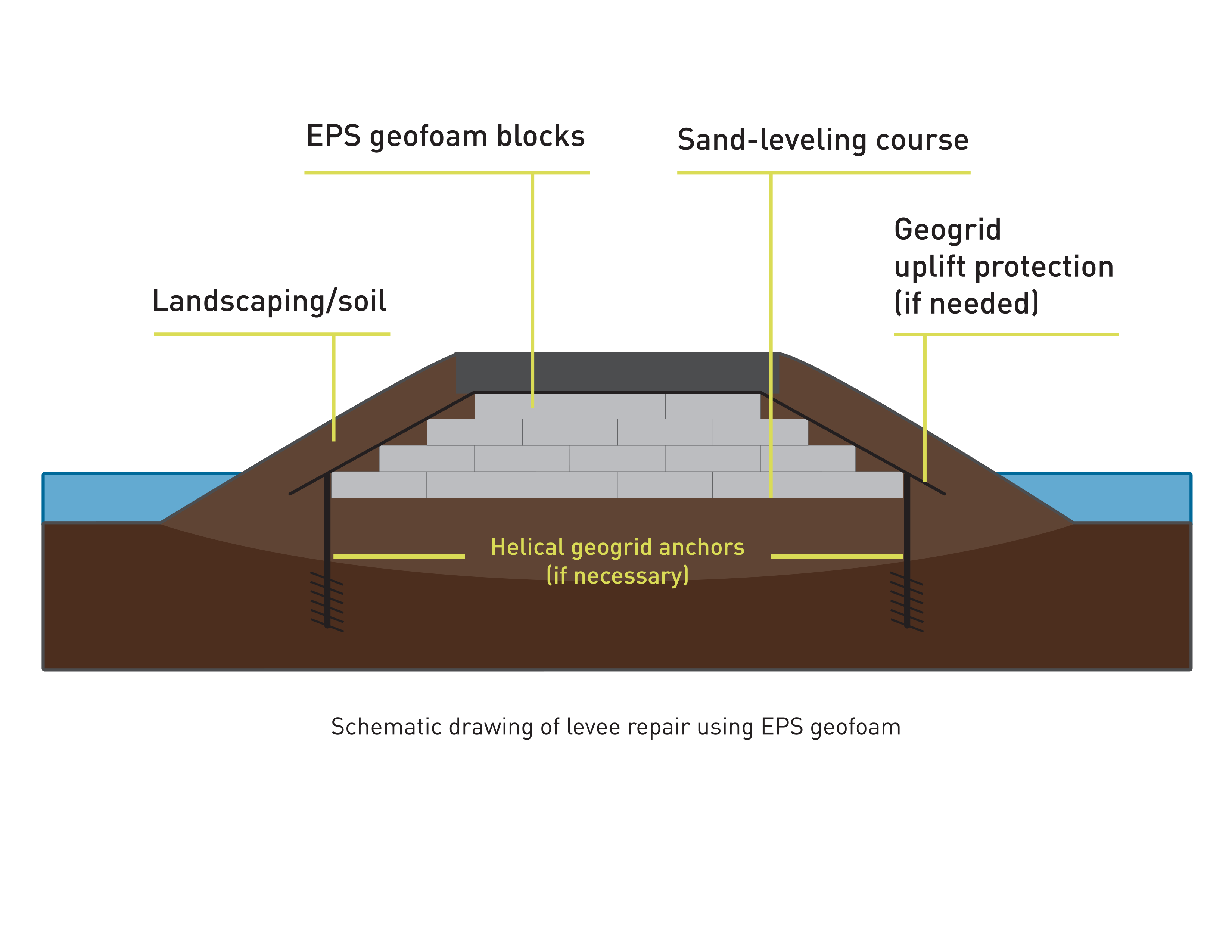
EPS geofoam can be easily installed to provide the volume needed to return the levee to its original configuration. And with approximately 1% of the weight of traditional soil fills, the use of EPS as fill reduces/eliminates additional stress and the cycle of settlement and levee raising. Of course, sufficient protective soil cover must be placed above the EPS geofoam. EPS geofoam can be easily handled at sites that have difficult accessibility and, if needed, EPS geofoam can be transported by barge.
To allow placement of the EPS geofoam, a portion of the existing levee is removed and stockpiled for reuse as soil cover for the EPS geofoam. A geotextile is used on the exposed subgrade to provide separation and improved stability. EPS geofoam blocks are placed on a sand-leveling bed and a geomembrane cover is used to encapsulate the blocks. A geotextile is placed over the geomembrane and the excavated soil is compacted over the EPS geofoam to bring the levee to its design elevation. These same principles can be applied to the construction of a new levee.
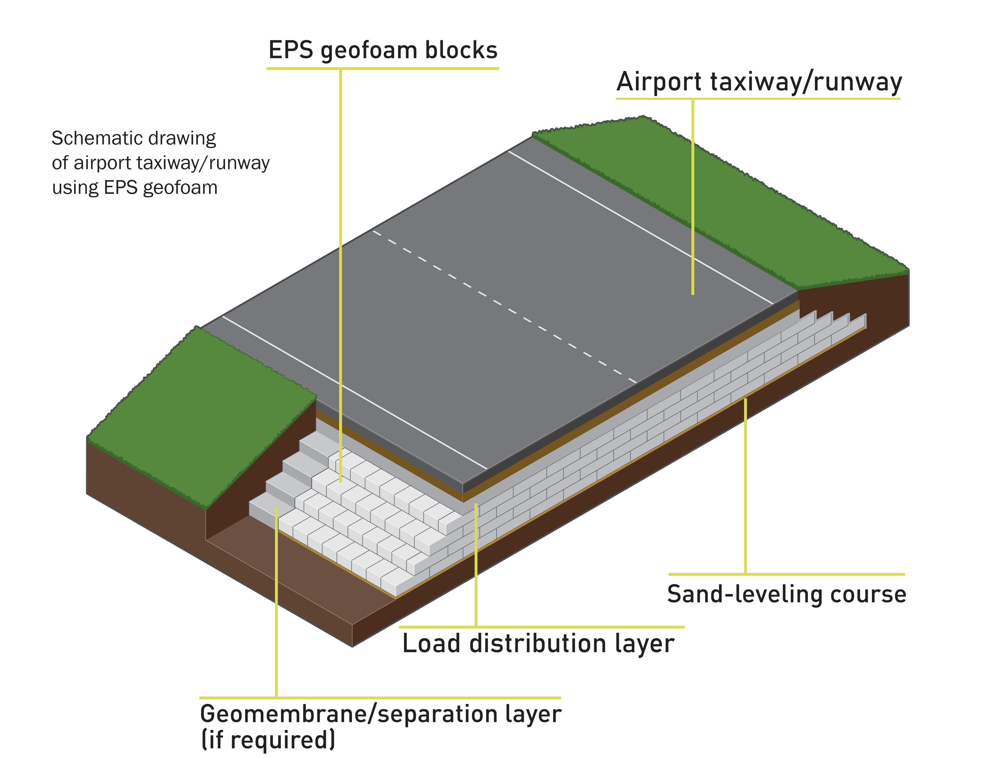
Similar to road construction, EPS geofoam can be used under airport runways to replace unsuitable soils without overloading the underlying subgrade materials.
This section describes some of the more unique applications of EPS geofoam in construction activities in North America. Some of these special applications include noise or visual barriers, expansive soils, earthquake mitigation, permafrost and rockfall protection.
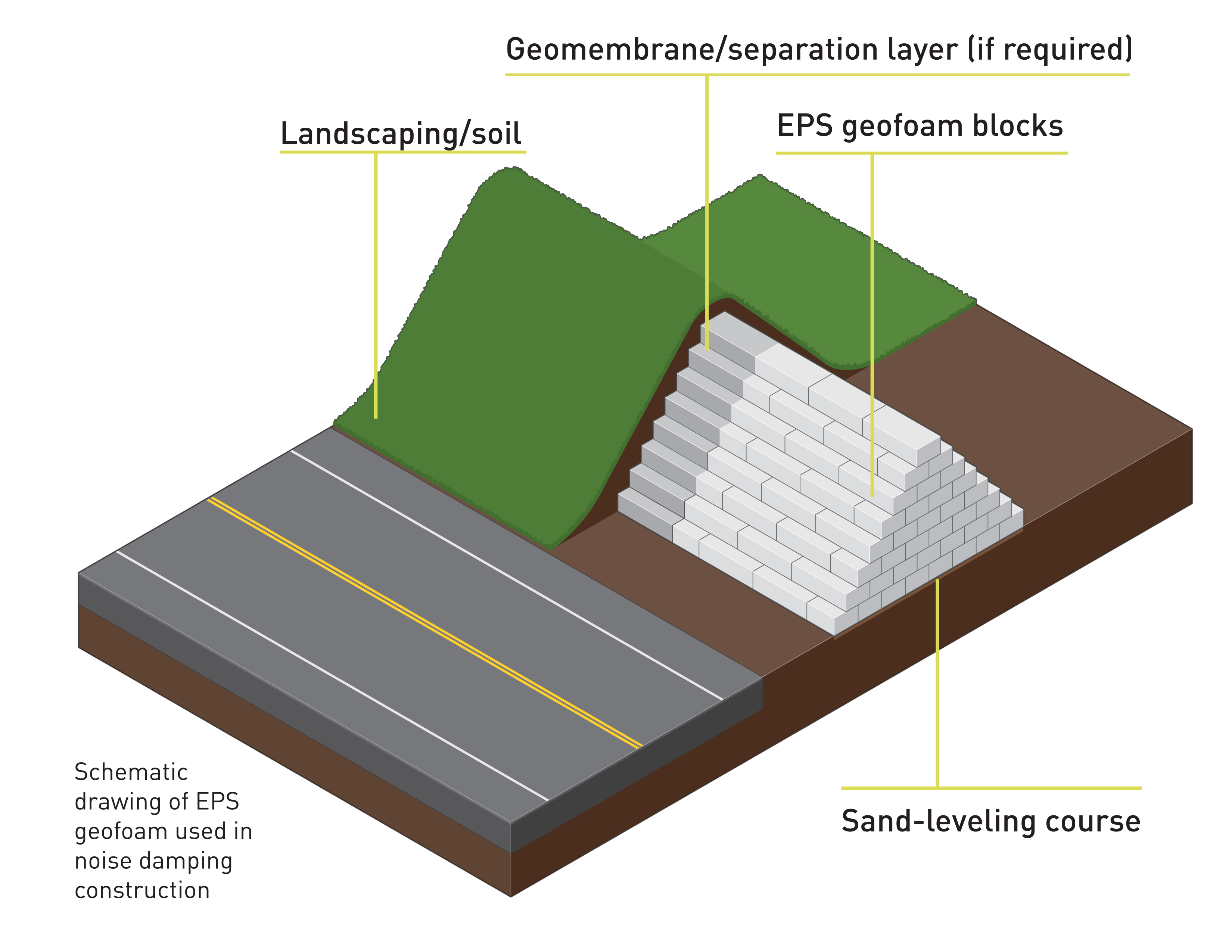
Noise and Vibration Damping
EPS geofoam can be used to build free-standing walls or embankments to reduce noise from highways. They can also be used to reduce the transmission of ground borne vibrations, for example, under railways or pavements, as part of the foundation of adjacent structures or as a cutoff wall between the railways or pavements and the adjacent structures.
Compressible Application
EPS geofoam is available in a wide range of compressive resistances. Compressible applications utilize the compressibility of EPS geofoam to accommodate ground movements. In contrast to most applications where EPS geofoam is designed for loading below the compressive resistance at 1% of the EPS geofoam, compressible applications are designed for strains beyond 1%.
Special Applications
When properly designed, EPS geofoam, when in contact with expansive soils, deforms and reduces the stresses transmitted to the relatively stiff structures by allowing the soils to expand, compress the EPS geofoam and not impact the structure. This means that the retaining structure or floor slab, built adjacent to or on expansive soil, only has to be designed for a small percentage of the forces that would be expected due to swelling or heaving of the expansive soil.
Seismic Application
EPS has two primary advantages that make it attractive for seismic design: its light weight and its compressibility. The low weight of EPS geofoam provides a significant reduction in the seismic forces imposed on buried structures, retaining walls, pipelines, etc., because the magnitude of the seismic force is proportional to the mass of the system, i.e., force equals mass times acceleration. Because EPS geofoam is moderately to highly compressible it can deform and act as a “buffer” to reduce the seismic energy imparted to the system. Numerical modeling of these buffer systems suggests that the horizontal seismic forces imparted to retaining walls and other buried structures can be reduced about 20 to 50%, depending on the thickness and compressive resistance of the EPS geofoam.
EPS geofoam embankments are stable during earthquakes based on post-earthquake performance observations from Japanese researchers. Other U.S. studies show that EPS geofoam embankments are inherently stable for small to moderate-size earthquakes. EPS geofoam has also been used atop and around buried steel pipelines to protect them from potential rupture during fault offset from a seismic event or other types of permanent ground displacement.
Permafrost Embankments
Roadways constructed over permafrost are susceptible to thaw settlement, which results in high maintenance costs and poor ride quality. The thaw settlement is caused by the permafrost thawing. The shoulders of the roadway tend to be the most problematic areas because there is less fill over the shoulders, which means less insulating material to prevent the heat from reaching the permafrost and causing thawing. Constructing an EPS geofoam embankment over the permafrost takes advantage of the insulating quality of EPS. The primary purpose of the EPS geofoam is to sufficiently insulate the underlying permafrost to minimize/prevent heat transfer into the frozen ground, which reduces thawing and thaw-consolidation of ice-rich permafrost soils to an acceptable level.
The light weight of EPS geofoam also induces little settlement due to increased stress even if the insulation effect of EPS geofoam does not keep the permafrost frozen. Finally, the ability to construct an embankment quickly and under adverse winter conditions is of great benefit in a climate with a short and unpredictable construction season.
Rockfall/Impact Protection
Development in mountainous regions sometimes occurs where there is a high probability of rockfall. Structures, roads and railways built in the trajectory of the rock need to be protected. Protection galleries can be a good choice when the area to be protected is relatively narrow and limited, like roads and railways, and safety in the area below the protected area can be neglected. Traditionally, rockfall protection galleries are constructed with a soil layer over their cover, which provides limited energy absorption. Adding a layer of EPS geofoam under the soil cover could greatly improve the performance of the protection gallery due to the high energy absorption capacity shown by EPS geofoam as it strains during impact.